INTRODUCTION
In conjunction with another senior project team, our intention is to design a system that allows isolated communities to process their own maize. More specifically, our team will design a drive that transmits power from a human-pedaled bicycle to various other machines, (primarily a grinding mill) via multiple gearing reductions. The residents of Kumponda, Malawi are intended to be the primary users of our project’s products. Our goals are to design and build a prototype, provide our sponsor (Mr. Wheeler) with detailed parts drawings, manufacturing instructions and an Operation Manual.
Crucial design challenges will be reliability, reparability, and manufacturability. The nature of the project constrains our building materials and fabrication to what is available in and around the urban center of Blantyre (population – 1 million). The Cal Poly Chapter of Engineers Without Borders (EWB) has attempted this project before on multiple occasions with mixed results. EWB will be provided with our design and the results we have concerning the first iteration and the testing performed. They will have the option to implement our design at their discretion, and we plan to work in conjunction with them to the extent that each of our groups may maximize results. Mr. Wheeler will also have the opportunity to implement the design as he chooses.
BACKGROUND
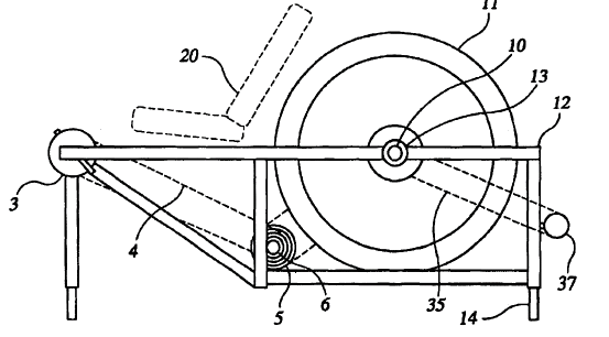
Figure 4. Basic schematic of the device described by US Patent #US6983948B2.
This patent, published on January 10, 2010, details a self-contained mechanical device that can be connected to various machinery, more-specifically applicable for less-industrialized nations. The device is composed of a pedal assembly, a power unit frame, a flywheel assembly, and transmission assembly. The patent is currently listed as expired. The fundamental aspects of the device are shown in Figure 4.
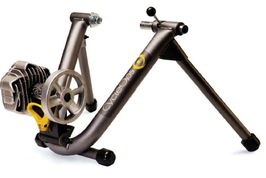
Figure 5. The Fluid2 Cycling Trainer pictured without bicycle.
The generic cycling trainer frame design, shown in Figure 5, is potentially applicable for project. It supports the bike by the rear axle and provides stability to the bike and rider during operation. The friction wheel is on an adjustable swing arm. The swing arm can be loosened by a bolt, adjusted to a new position about its pivot and then fastened again. The adjustable design accommodates 26”-29” wheels.
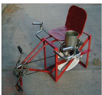
Figure 12. Full system.
We believe this flywheel option has strong potential for success in Malawi because of the material accessibility and the rotational balance provided by using the bicycle wheel as structure. The full system that utilizes the Concrete flywheel is displayed in Figure 12.
REQUIREMENTS
Discussion
For quantitative specification #1, efficiency, the 90% value refers to the ratio of the power our system receives to what it delivers. Our system will have as little frictional losses as possible but considering the potential variety in quality of parts available in Malawi we mainly expect to maximize efficiency. Furthermore, if our system happens to incorporate a full independent bicycle, we will be out of control of said bicycles frictional losses. The setup time parameter comes from our interview with Mr. Wheeler during which he expressed the importance of easy use. The wheel size parameter pertains to the anticipated use of existing bicycle components in our design (potentially an entire bike). The cost and output height parameters were given.
DESIGN DEVELOPMENT
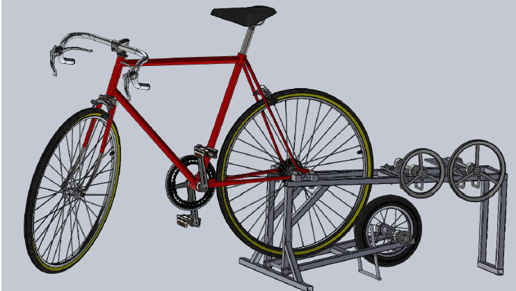
Figure 17 Full system assembly with 700c bicycle attached.
With our final system concept selected, we generated a preliminary design that conveyed the basic layout of system and showed how the components would interface with each other. Through revision based on feedback from our sponsor and further consideration within our team we have developed our critical design. Our critical design with a bicycle paired to the system is shown below in Figure 17. The main goal of this critical design is to detail the form and functions of the device and the method of power transmission from the user’s pedal power to the output shaft. The output shaft is designed to supply power to external devices such as the maize mill.
DETAILED DESIGN
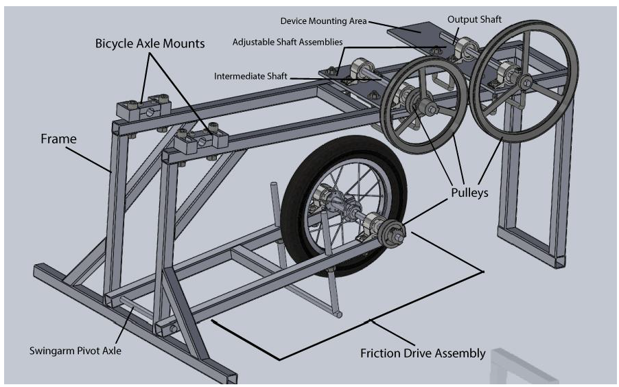
Figure 18. Sub-Assembly and Component Names.
These components are the ones that provide critical functions in the overall device. Screws, nuts and other smaller components will not be discussed in this section, but can be viewed in the Technical Drawings and Bill of Materials in Appendix K and Appendix N, respectively. The overall system is shown below in Figure 18 with the major components and sub-assemblies Annotated. Each component and sub-assembly is explained in detail in this section.
JUSTIFICATION
This section will explain the reasoning behind decisions made over the course of the detailed design phase. The major areas of consideration are the drivetrain, input output interfaces, adjustability, and structural concerns. Much of the challenge in this design project involves material availability and manufacturability. We expect fairly low levels of power through our system which is key to many of our decisions.
We performed the majority of our calculations for quantitative analysis and justification in an Excel document. We built the spread sheet to take values for user inputs (power, speed, bicycle wheel size, efficiency and gear ratio) and component sizes (pulley diameters, belt lengths). It solves for speeds and torques at each point in the system, minimum allowable shaft diameters, pulley center spacing, and allowable belt power. This method of analysis allowed us to perform many iterations to select the optimal components for the requirements we had to work with.
PROJECT PLAN
Verification Plan
The full design verification plan and report (DVP&R) is found in Appendix M. The DVP&R details the test plans for the system in order to determine how it satisfies the engineering specifications found in Table 1 and Table 2 of Section 3.4. We will evaluate the performance of our system on both qualitative and quantitative bases.
Simply put, our system should allow the user to operate the mill with maintainable ease. We will measure speeds at the slow output by counting revolutions and at high speeds with a non-contact tachometer. The primary purpose of the testing is to validate the design and generate ideas for corrective solutions as challenges arise from the manufacturing and operation stages.
MANUFACTURING
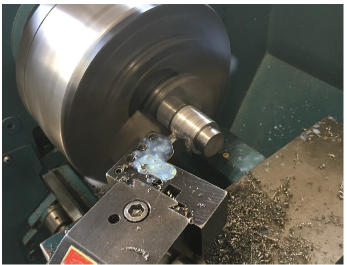
Figure 27. A photo of the cylindrical steel bar stock being turned on a lathe to match the inner profile of the bicycle wheel hub.
We first started with a 12” children’s bicycle wheel, and removed the hub’s internal pieces such as the bearings and axle. We had our ½” shaft to fit in the hub’s inner surface, which was about a 1 3/8” hole on one side and about a 1” hole on the other side. To fix the shaft to the hub, we found a piece of 1 ½” cylindrical steel bar, and turned it on the lathe to match the inner profile of the hub. A photo of this stock being turned on the lathe is shown in Figure 27.
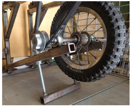
Figure 29. A photo of the completed friction drive assembly.
For our prototype, the bearings are mounted with ¼”-20 hex cap screws and ¼”-20 nuts. With the bearings mounted, thread one flange nut on each arm of the friction drive base’s threaded rods, then push the threaded rods through the corresponding holes in the friction drive swingarm. The assembled Friction Drive Sub-Assembly is shown below in Figure 29.
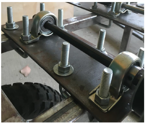
Figure 30. A photo of the completed intermediate adjustable shaft assembly.
With the base plates cut and drilled, both the intermediate and output assemblies can be put together. Refer to the Adjustable Shaft Sub-Assembly technical drawing to. Mount the proper bearings over their respective holes in the base plate and then push the U-bolts through their respective holes and fasten all the nuts securely. Please note that the U-bolts must also be mounted around the upper bars of the frame for the final assembly. See Figure 30 for a photo of one of the completed adjustable shaft assembly.
TESTING
A “catch-all” operationality test dominated our verification plan, and consisted of sustained ability to drive the fully loaded maize mill. Unfortunately, the mill was not completed in time for extensive testing of the coupled system. Various other tests allowed us to successfully determine the functionality and mechanical capability of the drive system. Thankfully, we were able to perform some tests with the mill team and clearly demonstrated our system’s ability to run their mill.
- Sub-system Testing
- System Testing
- Testing with Mill
- Tested Engineering Specifications
CONCLUSIONS
Our prototype successfully meets nearly all of the specifications that were determined as goals for the design based on problem we were tasked to address. The pedal powered drivetrain system is able to transfer power from a human comfortably and safely. The system enables the output power to be adjusted from high torque, low speed to high speed, low torque to accommodate various applications. The device can accommodate different sized bicycles and does not require the bicycle to be modified in any way. Attaching the bike to the device is quick and can be done with simple tools. During operation the bike, rider, device, and attachment are stable and safe. No components in the drivetrain slip or fail during regular or extreme operation.
The biggest concern our team had with our design was that the bicycle wheel to friction wheel interface would slip or that the belts would slip on the pulleys under high loads. The testing of our prototype verified that analysis was valid and that our system operates as designed under fully loaded conditions. During one test a pulley slipped on its shaft even though the set screw was fastened. We resolved this by grinding flats into the shafts so that they were d-shafts which completely fixed the problem. Otherwise there were no slipping problems during any of our testing. The use of a friction wheel is a viable method of transmitting power for this application assuming there is an adjustability to produce adequate normal force between the wheels, and the wheels have material with a good coefficient of friction, such as rubber to rubber.
The only requirement our system did not pass was vulnerability to corrosion. The steel frame and untreated shafts showed some rust after having been left outside for several days. We expect this is a condition the device could experience throughout its lifetime of operation. Our recommendation is that the non-coated steel components of the device be painted or covered with a different corrosion resistant solution to prevent rust. Rust will eventually lead to a compromise of structural integrity which may lead to failure and possibly injury.
Source: Cal Poly
Authors: Callaghan Fenerty | Geremy Patterson | Bradley Welch