EXECUTIVE SUMMARY
Greg Fields, the owner of Blend-It Winery and Bistro, wants to open an urban winery where the customers can automatically design their own custom wine blends. The project was worked on in conjunction by two different teams. One team which consisted of two mechanical engineers and one computer engineer were responsible for designing and building the physical system itself. The other team consisted of nine computer science majors who were responsible for developing the mobile applications as well as the server.
The teams designed a system that receives a wine blend order from a customer application and automatically dispenses the blend in the machine. The machine can be hooked up to five different kegs simultaneously, allowing for countless different wine blend combinations. The system uses a Raspberry Pi running Node-Red, as well as two Arduinos, to perform all of the logic operations in the system. The pouring for the device is controlled by electronic three-way valves which use infrared flow meters to accurately measure the amount of wine that should be poured. The following report breaks down the design, build and test process the physical device went through.
BACKGROUND
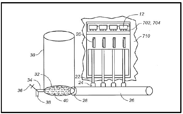
Figure 1: Patent #US20150336784 Schematic.
During the initial background research for this project we were unable to find any patents for designs that were similar what we envisioned. However, a few weeks ago, a patent lawyer, working for Greg Fields, found a patent(#US20150336784) that was almost identical to our potential design (Figure 1). The patent was filed by Napa Technology and is described as Wine Blending System and Method. The patent is vaguely worded and fairly all-encompassing so it covers most similar ideas.
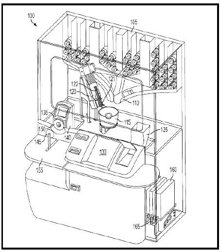
Figure 3: Overview Image from Patent #US8666540 B2.
Another product that has some similarities to our project is an Automated Color Dispensing System and Method, or Patent #US8666540 B2 (Figure 3), known colloquially as an automated paint mixing machine. The user inputs a desired color, then the machine selects a base paint color and then injects it with a variety of different tints that are determined by predefined color formulas.
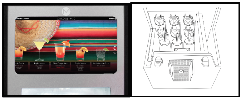
Figure 5: Monsieur Interface and Internal Design Drawing.
One final product that shares similarities with our wine blending device is the Monsieur automated bartender (Figure 5). For this device the user simply selects the drink of their choice from the built in touchscreen and the machine will automatically mix the corresponding ingredients in the exact amounts required. The Monsieur and our wine blending device are both capable of dispensing liquids in very accurate amounts; the Monsieur differs from our device, because it uses peristaltic pumps to draw the liquid from one of eight different ingredient containers while our device will use a pressurized valve. Additionally, because the Monsieur doesn’t dispense wine, it does not need to account for oxidation contamination.
DESIGN DEVELOPMENT
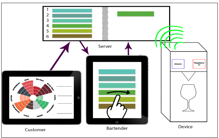
Figure 6: Use Case Graphic.
While working with the other teams, we envisioned various potential scenarios our device could encounter. For example, we defined the sequence, from start to finish, of how a drink order would go from being placed by the customer to being poured by the machine. This allowed us to visualize the communication between the device, server, and applications, and fostered discussion of possible impediments. See Figure 6 for a graphic overview of this example use case.
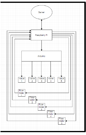
Figure 10: Microcontroller Responsibility Flowchart.
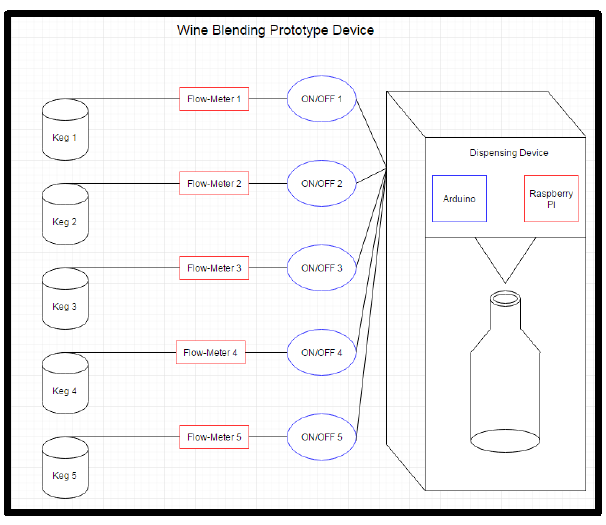
Figure 11: General Device Functional Diagram.
Preliminary discussions with the server team suggest that polling a server HTTP socket will be the best form of communication, but code design is not yet complete. In addition to receiving server instructions, the Raspberry Pi code will handle the feedback from flow-meters, report necessary information back to the server, and calculate valve open times to be sent to the Arduino. A chart showing the code outline and affected parts can be seen in Figure 10. A complete diagram of the device and the major components can be seen in Figure 11.
FINAL DESIGN DESCRIPTION
Figure 12: Final concept after CDR review.
Our final design has three major subsystems: electrical, mechanical, and software. We developed all three of these subsystems concurrently to ensure they cooperate together and all components work as desired. There are unique physical, electrical, and software tests that relate to all of these subsystems.
PRODUCT REALIZATION
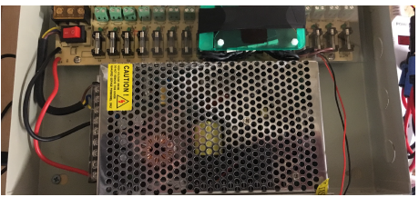
Figure 19: Power supply box.
The power supply that we purchased was modified to best fit the needs for our design. One modification that we made was to enlarge an opening on the side of the box to run the power cable from the supply to the power strip. We installed a cable clamp ring in this opening to ensure that the live wire could not be pulled loose from the box. Additionally, we added a small polycarbonate platform where we could mount the resistors for the valves. A picture of the interior of the power supply box is shown in Figure 19.
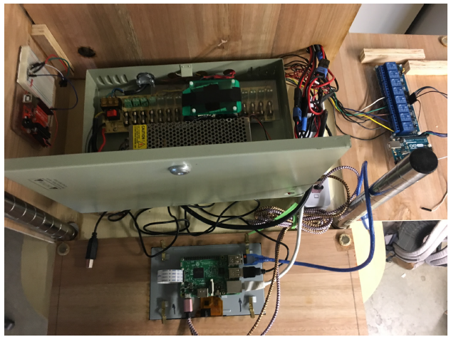
Figure 20: Electrical subsystem top view.
The relays were wired to the valve control Arduino, which uses its 5 volt pins to open and close the electro-mechanical switches in each relay. Each relay is also wired to its own channel on the power supply box. The 8-channel relay board is powered from the Arduino the controls them. This relay board has red LED’s on each channel to indicate the status of the relay (open/closed). The relays can be seen in blue on right hand panel in Figure 20 above.
Figure 37: Mounting tape along the edges of the top and bottom platform.
We first spray painted the Polyboard Cranberry Red and allowed it to dry. After we finished painting, we mounted the Polyboard to the frame of our device. The Polyboard was mounted to the exterior edges of the top and bottom platforms using 30lb 3M Foam Mounting Tape. Figure 37 shows the strips of mounting tape along the edge of the platforms.
DESIGN VERIFICATION (TESTING)
Our project testing can be broken down into 3 subsections and full system testing. Full system testing will not begin until each subsystem has adequately passed tests to our project specifications. The three subsystems include the mechanical, electrical, and software aspects of the system. Each of these subsystems has their own testing criteria and specifications they need to meet for our project to have full functionality.
- Mechanical Component Testing
- Electrical Component Testing
- Specification Verification Checklist
CONCLUSIONS AND RECOMMENDATIONS
Overall this project was a tremendous accomplishment. We feel as if we tackled two or three senior projects tied into one, and finished with a product that is both functional and aesthetically pleasing. There were, however, some things we would improve given more time. We had some trouble getting both Arduinos to simultaneously connect to the Raspberry Pi. There was not any simple way to view which port the operating system assigned to the board. Since Node-Red uses this port, code has to be changed if they switched for any reason.
We recommend creating “udev” rules to symbolically link each specific Arduino board to the port assigned by the operating system. By typing the command “ls -l /dev/valves” and “ls -l /dev/flowmeters” into the terminal, it is easy to see which port each board is connected to. Also, during the Raspberry Pi startup and upon redeploy in Node-Red, the Pi supplies voltage to the relay and therefore the power supply box. This means that the LED lights and valves will turn on during the computer startup and sometimes during the redeploy of code in Node-Red.
Our solution to this was to unplug the power supply box from the power strip during these times to mitigate the risk of accidental excitation voltage causing the valves to turn on without our control. If the lines are pressurized and the box is not unplugged, the valves will open without user control to close them, causing fluid to spill at a rapid rate. We think that further improvements to the code could allow for the Raspberry Pi to not supply voltage to the relay at these times and would solve this problem.
If this code is not feasible, a power switch mounted to the front panel could be added to effectively shut off valve power as we are currently doing by unplugging the box. Also, the code was limiting us to pour each wine separately with a delay between each. We think that with more testing we could achieve simultaneous pours of all five wines, making the process much faster. If this was not feasible, then it would be more realistic to add code that starts the next pour after the last was finished, eliminating the delay between wines and again making the process much faster.
Source: Cal Poly
Authors: Connor Clarry | Matt Moren | Russell Temple