EXECUTIVE SUMMARY
This document serves to outline the design and development of Sharpell Technologies’ ST5 electric vehicle drivetrain. Background research was conducted on various drivetrain components and testing methods, leading to the development of our drivetrain’s design requirements. Compiled in this report are the specifications of the components that will be integrated into our drivetrain design.
All component calculations and specifications can be located in the appendices. An in-depth manufacturing plan features the modifications necessary to create several key components such as the shafts and housing. The assembly plan details a step-by-step process in which the components are arranged to ensure a safe and functional drivetrain unit. Our drivetrain design will be validated through a series of static and dynamic tests, confirming that all the design requirements have been met, or exceeded.
BACKGROUND
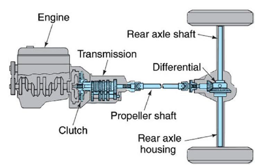
Figure 1. Typical drivetrain/powertrain layout in a rear wheel drive car.
The typical layout of the drivetrain in a rear wheel drive, front-combustion engine vehicle, consists of a multi-speed transmission that transmits power through a driveshaft to a differential. The power is then distributed to each of the rear wheels as shown in Figure 1.
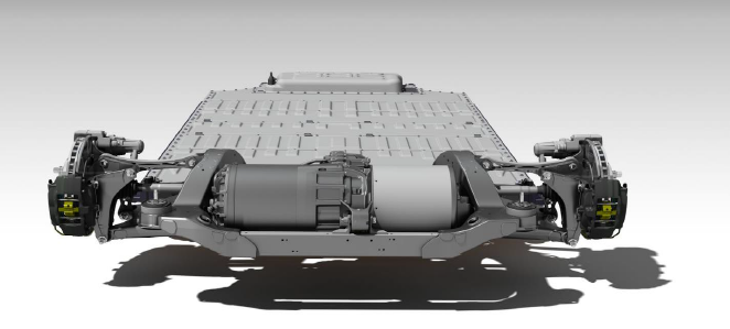
Figure 3. The Tesla Model S rear wheel drive vehicle with a drivetrain that is transversely mounted.
The differential in most electric vehicles no longer uses any type of bevel gear, and rather, uses solely helical gears. The reasoning behind only using helical gears is that the axes of the shafts in the gear reduction, electric motor, and axle are all parallel with each other. One example that uses this previous configuration is the Tesla Model S as depicted in Figure 3.
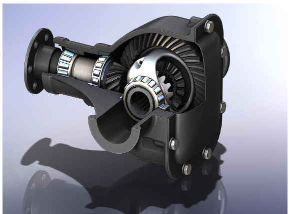
Figure 10. Vertical, transverse parting line as shown by the plate bolted on the back of the differential.
The housing encompasses the components surrounding the gears, differential, bearings, and also contains an oil bath to lubricate the inside for thermal transfers. The housing of most common drivetrains is made of aluminum or steel and has a vertical transverse parting line that runs parallel to the rear axle (please see Figure 10).
REQUIREMENTS
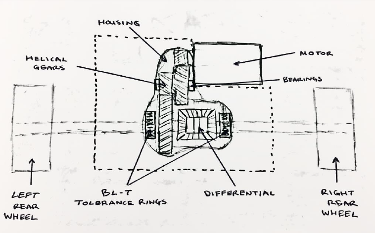
Figure 13. Boundary sketch showing the scope of our design which includes bearings, shafts, gears, differential, tolerance rings, and the housing.
Our goal is to design a drivetrain to deliver 700 lb-ft of torque at 6,000 rpm and 400 horsepower to the rear wheels of a 4,500 lbf vehicle. At the end of the year we will have a completed physical deliverable to present to our sponsor. The specifications listed above were received directly from our sponsor and were verified by benchmarking against existing quantifiable parameters from electric cars on the market such as the Roadster, Tesla’s Model S and X, and the Chevy Bolt. Other capabilities that are desired for the drivetrain are off-road driving in rugged terrain, and accelerating 0-60 mph in 5 seconds.
DESIGN DEVELOPMENT
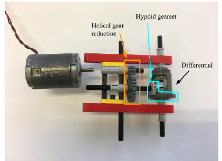
Figure 14. Concept 1: Longitudinally mounted motor with helical gear reduction and stock hypoid differential gear set.
Concept 1 mimics the layout of a drivetrain in a front engine, rear wheel drive vehicle. The electric motor’s shaft runs in the longitudinal direction of the vehicle. This requires a change in direction of the power transfer to the rear wheels, which is done by the differential. The differential remains in its stock form, minus the stock housing. A gear reduction coming off of the electric motor utilizes helical gears, where one helical gear shares the intermediate shaft with the pinion gear of the differential. The helical gear reduction along with the differential are packaged in one housing.
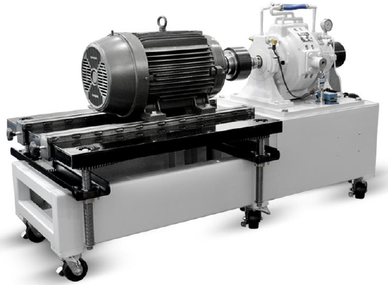
Figure 18. Electric motor on the left coupled to an absorption dynamometer on the right.
Due to the fact that the ST5 drivetrain simply transmits power, and does not create it, we will need to utilize a dynamometer with motoring capabilities in order to test it. Figure 18 shows the layout of how a drivetrain with axle shafts would be tested. We will need to locate a similarly designed drivetrain dynamometer that has two test stands capable of applying loads to the output shafts. The output shafts would be coupled to the test stands and the applied loads on the axle shafts will allow for torque to be transmitted through the drivetrain.
MANAGEMENT PLAN
To ensure the success of our project the following roles have been assigned. These positions are flexible and have the ability to change each quarter. Team roles shall include those listed below with their designated responsibilities and shall have the support of the other team members to accomplish the work.
- Design Development
- Assemble Prototype
- Cast Housing
- Test Prototype
- Delivering the Design
ADJUSTING TO NEW ST5 DESIGN
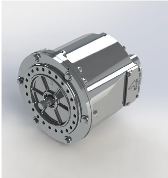
Figure 20. REMY HVH250-115 Motor.
The change to the ST5 prototype is that it will now be a dual motor design, using a less powerful motor at both the front and rear axles. Each motor would be capable of producing 310 lb-ft of torque. The motor that will be coupled with our drivetrain is the REMY HVH250-115 motor that is depicted in Figure 20. Our drivetrain design will still be coupled with a single motor, and then will be later duplicated for the motor to be located on the front axle.
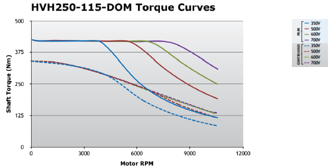
Figure 21. Torque output curves for the REMY HVH250-115 motor at various input voltages.
The driving factor for the acceleration is the REMY HVH250-115 motor’s torque and horsepower output. The solid blue line shown in Figure 21. graphically depicts the peak output torque of the REMY HVH250-115 while supplying 350V to the motor. This is the performance curve we are designing to, as instructed by Sharpell Technologies.
DESCRIPTION AND JUSTIFICATION OF FINAL DESIGN
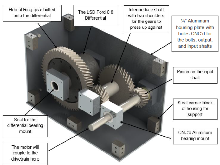
Figure 23. This figure displays our drivetrain layout including the four helical gears and the input shaft protruding from the housing.
Our final drivetrain design features a two-stage reduction. The two stage reduction allows for the drivetrain to achieve an 8.04:1 gear reduction ratio in a relatively compact design. Figure 23 below shows a CAD model of our drivetrain which is coupled to the motor for size comparison. The gears are able to handle the specified input torque of 400 lb-ft and increase this torque across the two gear sets.
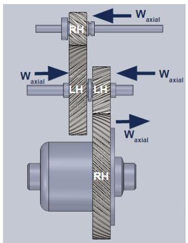
Figure 29. When operating in the forward direction, the axial loads from the gears will point towards the shoulders, providing enough support to constrain the shafts.
As noted, the helical gears impose axial forces on the shoulders of their respective shafts as seen in Figure 29. This is true when operating the vehicle in the forward direction, and when in reverse, the axial loads switch direction, causing a need for containment of the gears. To accomplish this, retaining rings will be used to constrain the gears on the shafts. In reverse operation, the drivetrain would be operating at a low speed and low torque scenario, applying relatively low axial loads.
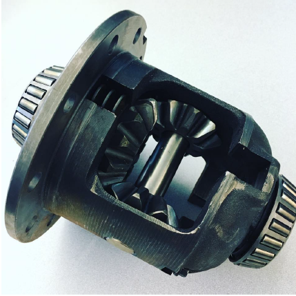
Figure 34. Ford 8.8” Traction-Lok Differential Gifted by Bair- Ling Technologies.
We acquired a Ford 8.8” differential for no cost, courtesy of Blair-Ling Technologies – shown in Figure 34. The differential supplied to us was from a donor vehicle with roughly 110,000 miles on it. Due to the relatively high mileage on the differential, it was decided that we will swap out the bearings with new replacements. Additionally, the spider gears and pinion gears of the differential will need to be replaced with gears that designed to retain an Independent Rear Suspension (IRS) axle set-up.
MANUFACTURING PLAN
The manufacturing of the housing will take place on Cal Poly’s campus utilizing the IME facilities, the hanger, and Mustang 60. For the CNC code needed to locate shafts and bearing locations, Trian Georgeou has graciously offered his expertise to help our team. Lathes and mills are also available to perform the other cuts of the stock metal for the drivetrain system and the manufacturing facilities are equipped with the other necessary tools required such as hydraulic presses to fit the bearings into bearing mounts, socket wrenches for housing assembly, drill presses for through holes.
DESIGN VERIFICATION PLAN
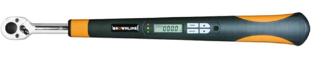
Figure 41. A common digital torque wrench.
We will perform simple static tests to verify the torque increase and speed reduction that is associated with our 8.04:1 gear reduction. The speed reduction test can be done by hand, where the input shaft will be rotated and verify that it will take roughly 8.04 rotations to produce a single rotation of the output shafts. The torque increase can be performed using digital torque wrenches as shown in Figure 41.
MANUFACTURING
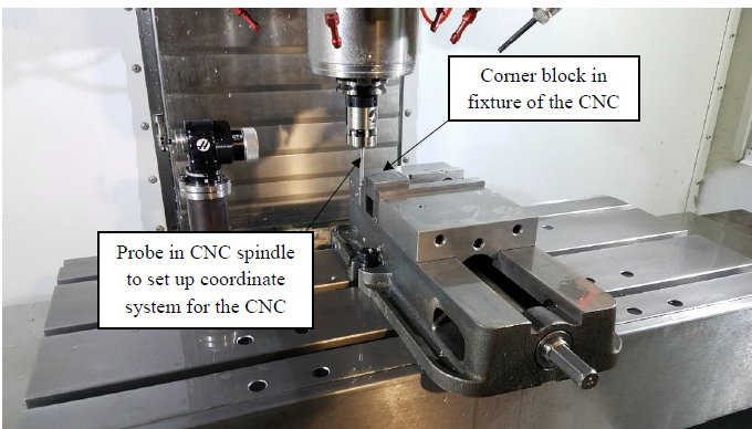
Figure 42. The probe located in the spindle is touching off a corner block in the CNC to give a reference location to perform the drilling operation.
To create the holes needed in the steel blocks we chose to CNC them for the precision required for the spacing of the holes and to make sure that they would align with the holes drilled in the housing plates. With the aid of Trian Georgeou, a professor in the IME department at Cal Poly, we were able to use Mastercam which created CNC operations based off our SolidWorks model. First, we probed the part to give the machine a datum to reference the operations off of as seen in Figure 42.
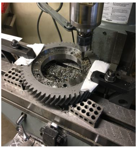
Figure 48. This is the fixturing used for drilling the holes in the ring gear.
Figure 48. This is the fixturing used for drilling the holes in the ring gear. The 3-2-1 blocks raised the gear off the mill table to allow the drill to move all the way through without marking the table. The toe clamps held the gear in place.
ASSEMBLY
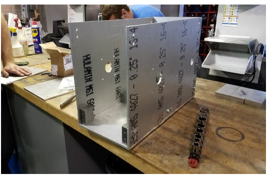
Figure 51. This is our initial fit up of the housing. Some of the holes in the housing plates had to be drilled a size or two bigger along with more facing done to the blocks to allow proper alignment of the housing.
Intermediate checks were performed throughout the manufacturing process to ensure that the proper tolerances were met for assembly. After all the housing parts were manufactured, we first bolted the housing together using a ratchet and socket set. Figure 51 shows the initial fit up of the housing. Fine tuning had to be done in order for the holes in the housing plates and corner blocks to line up while maintaining tight seams where no oil could leak out.
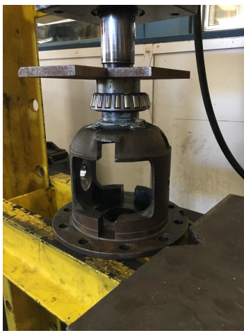
Figure 52. The hydraulic press with a small concentric tube to apply pressure to the inner race of the bearing without interfering with the differential.
Figure 52. The hydraulic press with a small concentric tube to apply pressure to the inner race of the bearing without interfering with the differential. The plate on top is used to evenly apply pressure to the set up. We also greased the outer circular portion of the differential to allow the inner race of the bearing to slide on more easily.
TESTING
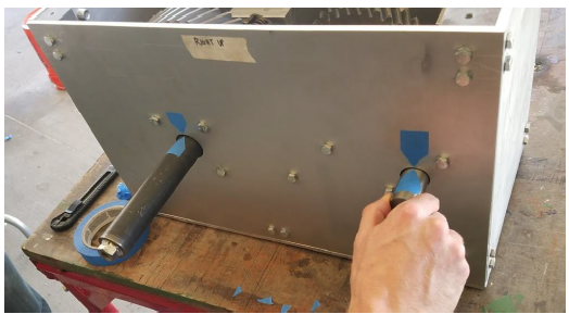
Figure 57. Our experimental setup was very simple and required very few additional supplies. The tape markers helped us keep track of the revolutions of each shaft.
Our test results matched what we designed for and predicted. The output shafts rotated 1 revolution while the input shaft rotated 8.04 revolutions. Our experimental setup is shown below in Figure 57.
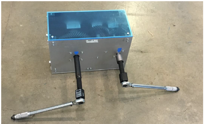
Figure 58. The input shaft with a torque wrench on the right-hand side is used to input the torque to the drivetrain. The corresponding output torque will read from the digital adapter coupled to the torque wrench on the left-hand side.
We do not believe that the varying torque splits from these trials reflect any issues with our drivetrain design. Instead, it showed that the equipment that we were using to conduct the test was not right for the job. We were unable to devise a way to simultaneously and equally remove the backlash from both torque wrenches, so we decided to conduct the test using only two of the three torque wrenches as seen in Figure 58.
CONCLUSIONS
Our drivetrain design concept came to full realization with our final prototype. No compromises or alterations to our design were made during the manufacturing stage and we were able to build our drivetrain concept exactly as planned because it was designed for ease of manufacturing. Additionally, when designing the drivetrain, we took into account the tools and resources available to us on campus, again allowing for the convenience and cost reduction of manufacturing with readily available equipment. Figure 60 portrays how the drivetrain build resembles the design concept.
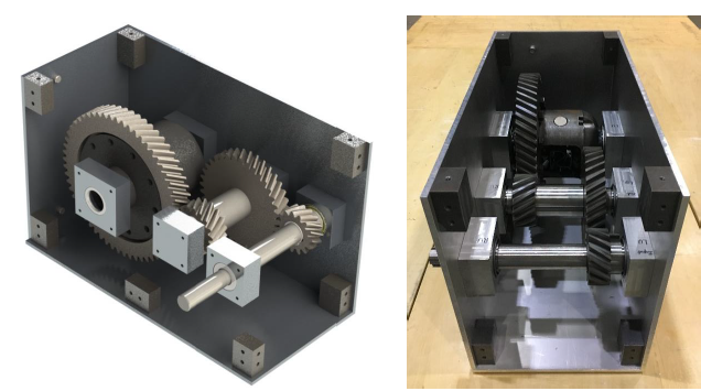
Figure 60. Side by side comparison of design concept (left) and the final prototype (right).
Due to the change in the application of our drivetrain, the system now is built as a one-off prototype for testing purposes and will not be mass produced to incorporate into the ST-5. However, after our sponsor implements the drivetrain into his prototype vehicle our system may become the basis for a further improved drivetrain system. Since Sharpell Technologies plans on duplicating the drivetrain for installation on the front axle of the prototype vehicle to create an AWD powetrain, our bill of materials will be a useful tool to determine what components need to be purchased and the overall cost of the actual drivetrain itself. Without the inclusion of labor and manufacturing processes, the drivetrain would cost $6,514.60. Please refer to Appendix F.21 for the bill of material’s component cost breakdown and Appendix F.22 for a detailed list of the vendor list and contact information.
Additional costs were incurred, in the form of tools and testing equipment. All costs associated with our senior project totaled $6,764.62 as detailed in the overall budget – Appendix F.16. We were successfully able to stay within our sponsor’s budget cap of $10,000.
Source: Cal Poly
Authors: Jimmy King | Kevin Moore | Charissa Seid