ABSTRACT
The Horizon Simulation Framework is a modeling and simulation framework developed to verify system level requirements. In this thesis, the framework is extended to include the Dynamic position type that existed in the early development phase of the framework. The Dynamic position type is tested through the modeling and simulation of a sounding rocket.
An active control system based on linear-quadratic regulator (LQR) control theory is implemented and tested in the simulation to determine the overall effect on altitude. A first order aerodynamics and aeroprediction model are created within the framework to allow for rapid changes early in the design process of the sounding rocket. The ight dynamics are compared to two different sounding rocket ights and the aeroprediction model is validated against public wind tunnel test data.
SOUNDING ROCKET MODEL
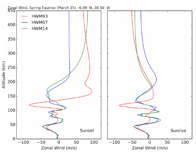
Figure 2.1: Horizontal Wind Model Sample Output.
The model used is the 2014 Horizontal Wind Model distributed by the Naval Research Laboratory [15]. It is is an empirical model based on measurements taken around the world and accounts for latitude, longitude, altitude, day of year, and time of day. The HWM provides measurements of zonal and meridional winds from 0 to 500 km.
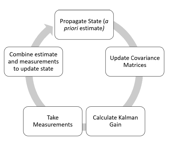
Figure 2.6: The Extended Kalman Filter Process.
The extended Kalman lter (EKF) is a method to use the Kalman lter for nonlinear states. The EKF accomplishes this by linearizing the state transition matrix at each time step through the use of the Jacobian. The state projection then takes the form
^xk = I + JkTs + …
which is the Taylor expansion of Jk about 0. The EKF also can be used for states with nonlinear measurements by following the same process for H. However, here the measurement is assumed to be linear.
SIMULATION IMPLEMENTATION
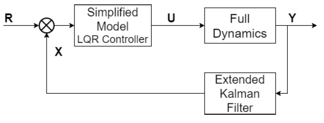
Figure 3.5: Control and Estimator Loop.
In this simulation, the fins are being used as the control surface. This means that only attitude can be controlled. To simplify the controller, the full state was not used as the input, but instead, only the Euler angles and body rates were used.
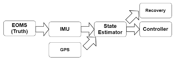
Figure 3.6: Subsystem Interactions within the Horizon Simulation Frame-work.
The HSF subsystems created, in order of evaluation, are shown in figure 3.6. The arrows show the dependency functions that transfer information in between each subsystem. The equations of motion (EOMs) are not a subsystem in HSF but feeds information into the other subsystems, so it is included in this description.
VERIFICATION AND VALIDATION
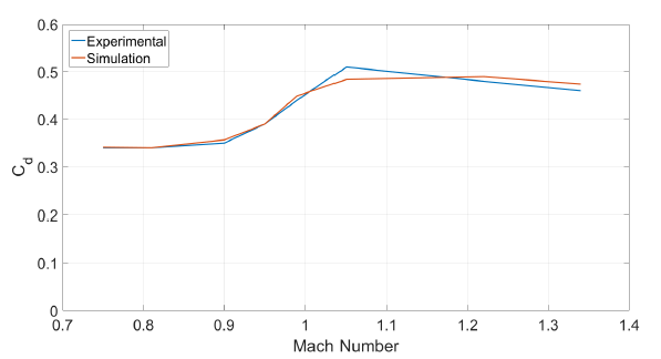
Figure 4.2: CD Comparison of Aeroprediction Data vs Wind Tunnel Data.
The experimental data compared to the output from the HSF aeroprediction method is shown in figure 4.2. There is good agreement between the two data sets. The largest error occurs at Mach 1.05, but it is hard to predict the aerodynamics at this speed because it is just after the point at which the vehicle goes supersonic. There is also a slight over-prediction of drag as the Mach number increases into the supersonic regime.
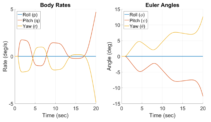
Figure 4.8: Simulated Euler Angles and Body Rate of Concord.
The final contributor to the trajectory error discussed here stems from the aerodynamic model. Figure 4.8 shows an oscillation in the pitch and yaw axes. Roll was assumed to be 0 in this simulation as no n cant was modeled. This oscillation occurs as the rocket tends to reduce the angle of attack to 0, but as a full aerodynamic model was not developed in this thesis, there is not enough damping to slow the attitude body rates as it approaches an angle of 0.
CONTROLLER DESIGN AND RESULTS
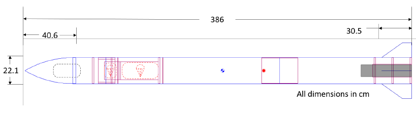
Figure 5.1: Outer Mold Line of Kronheim Rocket.
As part of the design process of the sounding rocket, an investigation of the altitude gain by including a control system on a sounding rocket is performed. The Kronheim rocket, developed by Cal Poly Space Systems, is used to test the simulated control system in both the uncontrolled and controlled results.
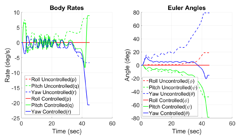
Figure 5.5: Angles Comparison of Controlled and Uncontrolled Flight.
Immediately it is seen that the controller has a positive effect of the altitude of the control system. The controller effect can also be seen in the plot of Euler angles and body rates ( figure 5.5). As mentioned the simulation tends to underdamp the oscillation around the zero degree angle of attack. which is also observed here. As expected, the controller acts as a damping term on this oscillation, but the stable design of the rocket means that the control fins do not have enough control authority to damp this oscillation out completely.
FUTURE WORK AND CONCLUSION
Future Work
As noted in section 4.2.1, the aerodynamics model used in this thesis had difficulties with oscillations around a 0 angle of attack. To remedy this issue two sections of the simulation must be updated, the equations of motion and the aeroprediction code. If just the EOMs are updated to account for more coefficients and these coefficients are provided by external files, the simulation will become more accurate. After the EOMs have been modified to accept more than the current aerodynamic coefficient, the aeroprediction code can be expanded to increase the fidelity of the model.
Along with these changes to the code to increase the fidelity of the simulation, aerodynamic unit tests to validate the predicted coefficients should be implemented. Currently, only one set of data is included in these tests, and while the simulation model agrees well with this data set, additional data sets will improve confidence in the model.
Conclusion
The HSF framework was developed to be modular and flexible. It was originally designed around scheduling tasks on a satellite and optimizing the value of these tasks in the system. However, in this thesis, an expansion of the framework capabilities is developed to re-implement dynamic motion types that existed in early versions of the framework.
To test this expanded capability of the framework a sounding rocket model was developed to predict performance and a control system was implemented to improve the maximum altitude reached by the rocket. To fully develop the model and make the framework self-contained, a first order method was implemented to predict the aerodynamic coefficients. The sounding rocket model was compared to two different experimental flights, and the aeroprediction model was compared to experimental data. Both of these comparisons showed relatively good agreement between the simulated and experimental data.
Source: California Polytechnic State University
Authors: Steven MacLean