EXECUTIVE SUMMARY
Since many tables currently used at Cal Poly are not ideal for active design situations, we have designed, built and tested to be used in design classrooms with an emphasis on using the tables to quickly prototype ideas. This table is a standing height table in a trapezoidal shape which can comfortably seat four people. The modular design of the table allows multiple tables to be use to create di erent shapes so that the tables can be used in multiple ways.
BACKGROUND
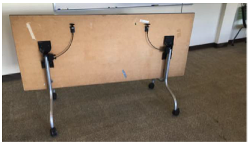
Figure 2.3: Table located in the Bonderson Project Center room 104, a collaborative space often used for group work and club meetings.
In the Bonderson Project Center, room 104, there are collapsible, folding tables made out of particle board, which are easy to reconfigure. A problem with the deployment mechanism occurs when it often fails to trigger properly, making a quick folding of the table surface difficult. The deployment mechanism seen in Figure 2.3 is one that uses a cable to engage or disengage locking pins. These tables are also reasonably unstable because they are supported at just two locations and can collapse if they are not properly locked into place.
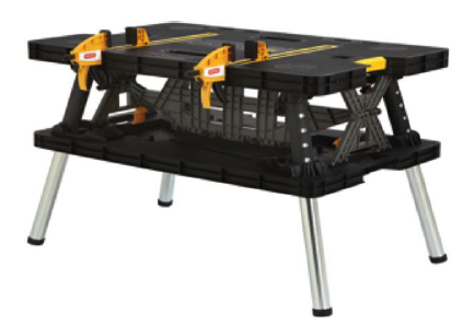
Figure 2.7: The Keter worktable, which sets up in 30 seconds.
The Keter worktable is notable for its quick deploy mechanism. With a 30 second setup time and an ability to support up to 1000 lbs., the Keter folding worktable has a strong design. Other than this, the Keter table is not the most aesthetically pleasing table on the market, as seen in Figure 2.7. It also does not accomplish the task of being able to comfortably seat/stand four people working in a common area.
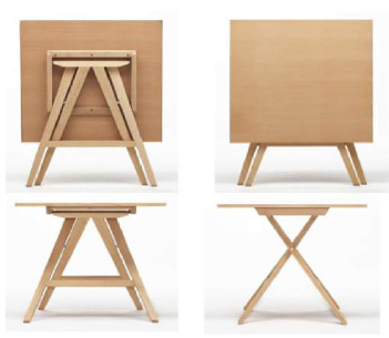
Figure 2.9: A creative folding mechanism.
A creative folding mechanism is displayed in Figure 2.9. Without knowledge of the weight capacity and overall stability of this easel-style table, we cannot make any definitive remarks about the functionality of the table. However, its interesting folding mechanism is something to consider when designing a new surface.
OBJECTIVES
Currently, tables used in collaborative workspaces on the Cal Poly campus are either not stable or not portable enough to foster a productive environment. Design students need a way to collaborate on projects while still being able to reconfigure a room to allow it to be multipurpose. We intend to design and fabricate a worktable to be used in Cal Poly design spaces that is cost-effective, stable and robust, while being portable and stores compactly.
The ultimate goal of this project was to produce a functional prototype to be demonstrated and initially evaluated at the Senior Project Exposition hosted by Cal Poly on June 2, 2017. This prototype was to satisfy the customer requirements to the best of our design ability in compliance with the engineering specifications. The success of the project will be determined by testing the compliance of the final prototype to the engineering specifications.
METHOD OF APPROACH
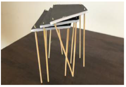
Figure 4.9: Concept modeling of small stacking tables.
The last ideation session held was a session where we created some of our top design ideas using foam core and basic crafting supplies. Out of the roughly 150 sketches generated over the course of the six prior ideation sessions, six main designs were created during this session. The designs are seen in their multiple configurations in Figure 4.9
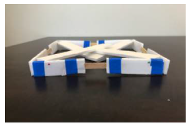
Figure 4.13: Concept modeling of “The Square”
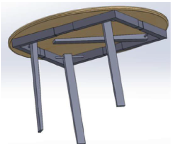
Figure 4.20: The Square table.
The basis of this design is an expandable base with changeable height legs, which can be adjusted to t any surface shape as seen in Figure 4.13. The SolidWorks model can be seen in Figure 4.20, which displays the standing and collapsed state of this table, simultaneously. This design is compelling because it is adaptable for nearly any type of surface which may be used with it, since the base is able to expand or collapse based on the size and shape of the table top.
SELECTED CONCEPT
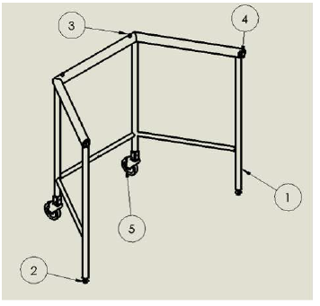
Figure 5.9: Isometric view of the frame with components labeled as follows: 1-Welded Frame Assembly, 2-Leveling End Cap Assembly, 3 – Locating Pins, 4 – Latch Assembly, 5 – Caster Assembly.
This is accomplished by setting pins into the frame to locate the corresponding holes drilled in the table surfaces (feature 3) and by adding magnetic latches to the back of the frame to secure the table tops in place (feature 4). The combination of these features is brought together in Figure 5.9 where we see a labeled drawing of the full frame model.
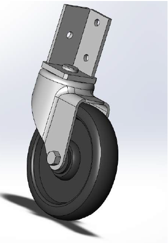
Figure 5.23: Solidworks model of the selected caster.
The ability to rotate 360° allows the table to be easily moved about a space when the back two legs are tipped up, so that the table acts as a walker. Due to the width of the frame at 48 inches, it is important that a table is able to be turned so that it fits through small spaces without requiring the user to exert much effort. The casters selected, detailed in Figures D.5 and D.6, were selected due to their strength and ease of attachment to the legs of the table which can be seen in Figure 5.23.
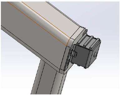
Figure 5.25: Solidworks model of the magnetic latch attachment to the end cap.
Steel end caps are required to have an enclosed surface for the top portion of the table. The steel end caps enclose the surface and allow for the magnetic latches to be easily attached to the back end of the table as seen in Figure 5.25.
MANUFACTURING
The fabrication and assembly of the frame and the surfaces of the table can be done entirely in house. Materials have been selected so that the tables should be able to be easily reproduced on a more major scale. This ability in the future for quick manufacturing will delivery a product in a timely fashion.
- Frame Manufacturing
- Active Design Surface Manufacturing
- Formal Surface Manufacturing
- Maintenance and Repair
- Safety Overview
DESIGN TESTING
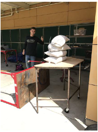
Figure 7.4: Full loading of sand bags over the unsupported edge of the table.
In Figure, 7.4, three sand bags were added to the initial sand bag to bring the weight over 200 lb, which was specified to be tested as a point loading condition. Due to the deflection of the table with four sand bags over the free hanging edge, further sand bags were not added due to the concern for causing permanent damage to the surface.
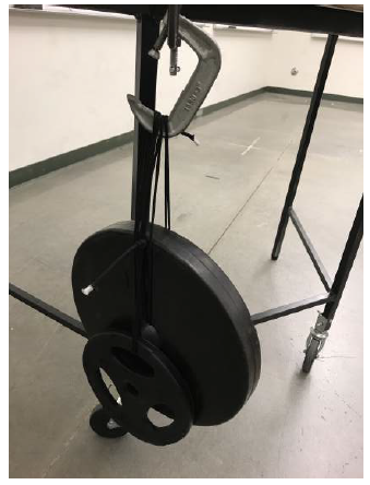
Figure 7.18: Maximum loading on the right corner before pop off occurred.
The final load applied to the table before pop o was 40 lb, seen in Figure 7.18. We can see the maximum loading to the table before both back latches detached from the back channel. However, like with the front left corner, not being able to support a load of 200 lb causes the front right corner to also be a failure.
RECOMMENDATIONS AND CONCLUSIONS
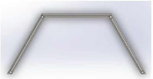
Figure 8.1: Reoriented legs to allow for better ease of manufacturing.
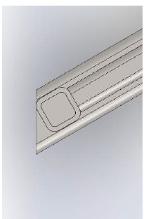
Figure 8.2: Lower supports would be perpendicular to the back legs.
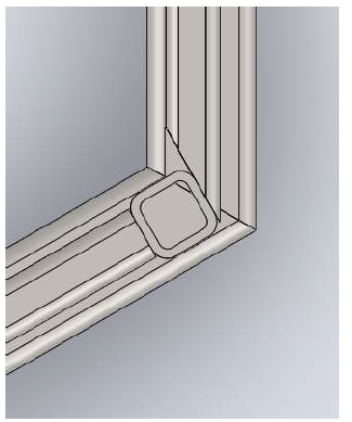
Figure 8.3: Side supports are perpendicular to the front legs as well while front support is now the only piece cut at a severe angle.
Before more of these table are to be made, there need to be more considerations made for ease of manufacturability. There are two approaches that could be taken to make these tables more east to manufacture, particularly when it comes to welding the frame together. The first would be to redesign the table to alleviate the difficulty in welding table together at the 60° angles.
To do this, the orientation of the legs could be changed to allow for the sides of the tables to be welded together before they are attached to the top surface of the table as demonstrated in Figures 8.1, 8.2, and 8.3. The only part of the design that changes here is that the front bar is a 24″ piece with 30° angles cut into its front sides and the side bars have been shortened to about 21″.
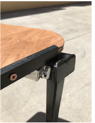
Figure 8.5: PVC sleeve inserted into the surface.
In addition to this, the surfaces, being made in accordance with the drawings provided in Appendix D do not line up as expected with back of the table as seen in Figure 8.5. This is primarily due to the location that the holes for the pins were placed. In the future, the pins should be located about .75 inches closer to the front edge of of the surface so that the channel is able to hang off of the back edge of the table and fully engage with the magnetic latches which should be placed on the back edge of the table.
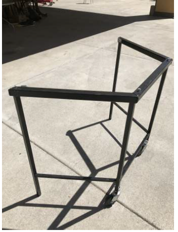
Figure 8.8: Final frame.
Upon completing the final table, some clear changes that need to be made are immediately apparent. First, the design changes mentioned above must be made so that the table is easier to manufacture and more aesthetically appealing. Other than the latch location on the back surface of the frame, it matches its intended design. As seen in Figure 8.8.
Source: California Polytechnic State University
Authors: Kelsey Ishimatsu Jacobson | Andrew Whitney