EXECUTIVE SUMMARY
This report documents the design and fabrication processes involved for the creation of an interactive science exhibit for the Grover Beach Exploration Station. This is a student-led senior project advised by Sarah Harding, professor of mechanical engineering, as a part of California Polytechnic State University in San Luis Obispo’s mechanical engineering program. The final product is a fully functioning, durable system that is capable of pumping and recycling water throughout use when users are in its vicinity.
The exhibit is to be considered in 4 main subsystems: basin, plumbing, frame, and sleep mode system. A fiberglass basin that holds all the water in the exhibit sits recessed inside a welded steel frame. Water is pumped through the bottom of the basin from within an enclosed storage area inside the frame, and is recycled back into the water reservoir by placement of two weir valves. A submersible pump powers the exhibit, and is controlled by passive infrared sensors that activate when human presence is sensed within 15ft. While the manufacturing process did reach completion, testing and verification did not. However, proposed testing plans are still included in the appendices of the report for informational purposes.
Divided into distinct sections, this report will enlighten the reader on each part of the design process. First, background research and preliminary design explains the methodology of developing the vision of the final design. Next, different design analysis techniques are given for each respective subsystem of the proposed exhibit. An in-depth description for manufacturing and testing of the completed exhibit is given for each subsystem. Finally, recommendations are given for future improvements to the exhibit, and what kinds of different decisions would be made in the design process if given a second iteration.
BACKGROUND
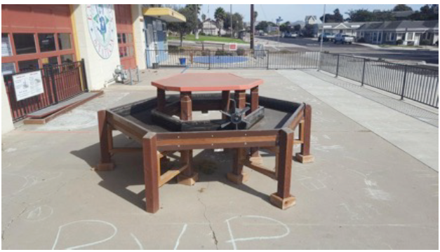
Figure 1: Current water table on the front patio of the Exploration Station. Exhibit is not currently in use.
During our first interview with our sponsors, we were made aware of their current water table exhibit that is located on the front patio. We discussed the possibility of refurbishing/restoring the existing table by making the features more interactive, educative, and fun while also structurally reinforcing the table. We were given permission to use the current table in its entirety, to use components of it, or the freedom to design a completely new interactive water exhibit. The current water table exhibit is shown in Figure 1.
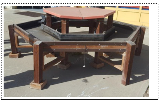
Figure 3: The support leg on the front right side of the exhibit is missing wooden trim piece for balance.
We then observed the frame of the water table and its condition. The frame of the exhibit is constructed with treated wood (2X4’s and 4X4’s), sheet metal, nuts, bolts, and nails. Some wooden members were missing around the legs of the supports and the remaining leg pieces were loose. Figure 3 shows the frame along with the missing legs’ trim pieces.
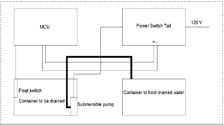
Figure 7: Wiring diagram for draining water from one container to another.
Figure 7 shows an automated way to drain water from one container to another when the water level reaches a certain height. When the water level rises in the container to be drained, a component of the float switch goes up and that sends a signal to the microcontroller. The microcontroller then sends a signal to the power switch tail to turn on the relay inside it. The microcontroller is essentially turning on a 120 V line since the power switch tail is connected to an outlet providing that voltage. It’s worth mentioning that 120 V is standard for most homes.
DESIGN DEVELOPMENT
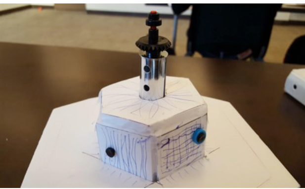
Figure 11: Hexagonal Prototype with Water Wall.
Below, Figure 11 shows a hexagon shaped water exhibit with a usable area in the middle. The existing water table at the Exploration Station has the same shape, but with an unusable center area. For this prototype, we placed a water dome at the top of the middle area of the exhibit. The runoff from the water dome cascades down and supplies the water flow necessary for the magnetic water walls to be interactive for its users.
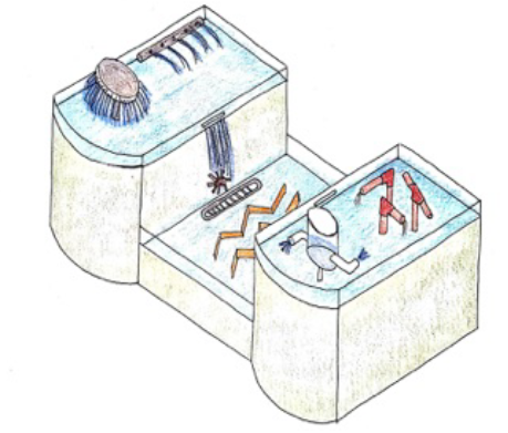
Figure 16: Drawing of feature layout for the Baby B final concept design.
The first of our two final design concepts is what our team has named the Baby B. Figure 16 shows the artistic sketch that we have created to help visualize what the Baby B concept would look like. This concept is a “B” shaped table with an extended midsection to be used as a play area catering to smaller visitors (ages three to six) who might not be able to reach up to the taller features. This table shape earned the highest total score in its respective Pugh matrix.
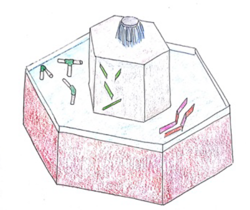
Figure 17: Drawing of feature layout for the Hex final concept design.
The second conceptual design we developed is the hexagonal hat. Figure 17 shows an artistic rendering of how we envisioned the hexagon design. The overall concept shape is similar to the existing water exhibit at Exploration Station with some creative modifications and material choices. We liked the fact that the existing water table can accommodate many visitors and the geometry of the hexagon is not very complex.
FINAL DESIGN
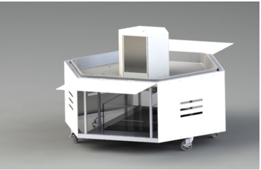
Figure 18: Solidworks rendering of the proposed Exploration Station water exhibit.
Our current design has a durable fiberglass basin, a steel frame capable of housing all necessary equipment internally, a submersible pump capable of sending water to a number of outlets across the basin (which can be later utilized for features), and programmed power saving sensors all included in an exhibit that will be aesthetically pleasing and be sure to draw a crowd. The three dimensional model of the proposed exhibit can be seen below in Figure 18.
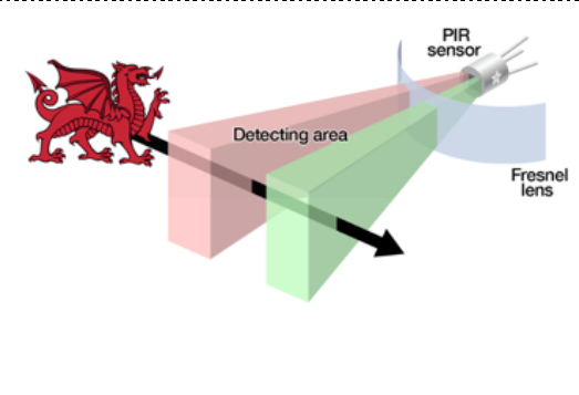
Figure 37: Detection area of motion sensor.
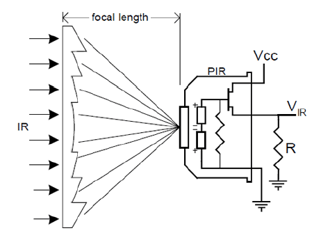
Figure 38: Effect of lens of incident radiation.
This is how the passive infrared sensor detects motion and it is called passive because it does not use any energy for detecting purposes, rather it uses the energy of the objects in its field of view. The dome that covers the metal casing serves to increase the detection area by directing the incident light towards the window inside. If we did not have this lens then the detection area would be two rectangles inside the metal casing as shown in Figure 37. The effect that the lens has on incident light is shown in Figure 38.
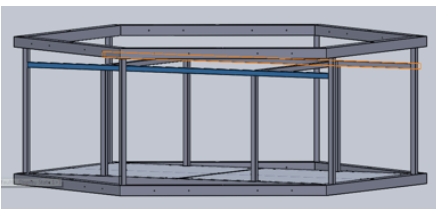
Figure 50: Vertical member in frame to undergo loading.
We have a few cross members that will be supporting the load and we wanted to make the cross bars sure did not have a deflection greater than 0.1 in. that can be seen highlighted in Figure 50. We again overestimated the vertical load to be 1500 lb-force acting directly in the center of the exhibit. Using the deformation equation of a simply supported prismatic elastic beam.
PRODUCT REALIZATION
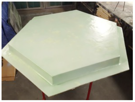
Figure 53: Basin mold with after the final layer of PVA mold release was applied.
One extremely light coat of distilled water makes all of the PVA spread and smooth out, creating the perfect surface finish for the laminate (because PVA is water soluble). Once the basin was left to fully dry, the surface preparation was completed. Figure 53 shows what the basin looked like once the final layer of PVA was applied. If desired, the user could use their fingernail to peel off a tiny bit of the edge of the laminate just to check thickness of the mold release layer.
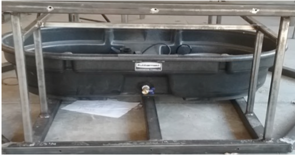
Figure 57: Drain assembly installed in reservoir tank.
The edges of the holes were finished with a metal file to ensure that the fitting would fit flush with the surface. After filing, the PVC bulkhead was inserted into the hole and tightened. Next two PVC adapters along with the ½ drain valve were installed into the bulkhead fitting with Teflon tape wrapped around all threads. This completed the install of the required drain on the reservoir. Figure 57 shows a picture of the installed bulkhead and drain assembly in the reservoir.
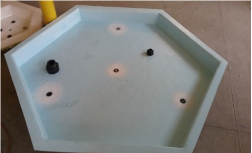
Figure 59: Holes drilled in fiberglass basin to test fit bulkhead fittings.
After the holes were drilled in the fiberglass basin, it was time to install the PVC bulkheads that would create a tight seal to prevent leaks and also make connections to attach vinyl tubing supply lines. Figure 59 shows a picture taken after drilling a few of the smaller holes in the fiberglass basin to accommodate the ¾” bulkhead fittings. With a few initial holes drilled, we were able to test fit the bulkheads into place to determine fit.
DESIGN VERIFICATION
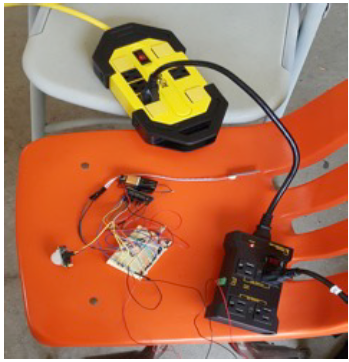
Figure 60: Testing triggering distances for PIR sensors.
The triggering distance of the sensors can be changed from 9ft to 21ft and we tested one sensor at its lowest setting because that is the setting that will be used for all sensors. We tested this by starting 20ft away from the sensor and walking towards it while monitoring whether motion was detected using the Sleep Mode App. The max distance where motion was detected at the lowest setting of the sensor was 15ft, unlike the datasheet of the sensor stated.
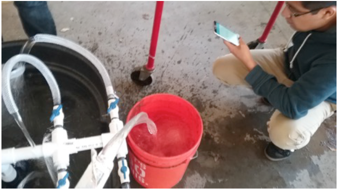
Figure 61: Measuring flow rates from an outlet tube.
Since the reservoir, pump, and PVC piping components were completed early and the final fiberglass basin would not be completed until later in the quarter, we felt it would be good to test for the desired flow rates from an outlet hose without the basin to get a basin on performance. We completed this test similar to the method we used when testing the prototype back before CDR. This method consisted of recording the time it takes to fill a five gallon bucket assuming that every time we filled the bucket it was near five gallons collected. Figure 61 shows a picture during a flow rate testing trial conducted by our group.
CONCLUSIONS AND RECOMMENDATIONS
Should our team have the opportunity to go back and proceed with a second iteration of exhibit design and manufacturing, there are a number of changes that we would make. First, it is recommended that (should the shape of hexagon be decided on again) then the team should design and machine our own lugs for fixing together pieces of the frame. The number of issues that this geometry created for our team throughout the project was fairly considerable.
When the frame steel was cut using the chop saw, inconsistencies in finish tolerances led to us having to improvise the forming of joints. Had we been able to use 60° square lugs (which we were not able to find on the internet) then it would have made frame assembly much easier, and if compatible materials for beams and lugs were chosen, then the two could have been welded together for additional support.
Another change that our team would make is using a material other than stainless steel for the frame of the smaller hexagonal structure in the middle of the basin. The weight of the frame is a concern, and causes a lot of unwanted deflection in the very middle, which can be considered one of the causes for the leaks that we are currently experiencing from the bulkheads in that area. Using another material, such as PVC or some other kind of plastic would be less expensive, easier to manufacture, and place less stress on the extremely valuable basin that it is resting upon.
Additionally, the drains that we have installed do not allow for very much flow out of the basin and the reservoir. More functional drains with a wider valve opening size would be installed in these locations to allow for more efficient draining of the system. Also, for the drain on the reservoir, we did not take into account that the user cannot just attach a hose and funnel the water wherever they want. A certain amount of head is required to move a fluid, and having the outlet tap at the bottom of the tank does not allow for this.
Source: Cal Poly
Authors: Alejandro Gonzalez-Smith | Raymond Morales | Heriberto Rodriguez | Nicholas Runyan