EXECUTIVE SUMMARY
The goal of our project was to construct a new jogger for a young man name Joseph Cornelius with spastic quadriplegia. Joseph enjoys participating in marathons on his jogger and has been an inspiration to many. However, his jogger has been worn down with the foot rests breaking often due to the immense force he exerts on them. The old jogger itself did little to provide comfort to Joseph as he would experience the bumps on the road which was issue especially as his right femur is dislocated from his hip making his right hip sensitive.
With comfort as key in our design, we decided to make a new frame from scratch. The components of the new jogger were divide into parts with Luke Kraemer in charge of the frame, Robert Trujillo in charge of the seat, Carolina Reyes in charge of the harness, and Josh Egli in charge of the sunshade canopy and finances.
Some issues in our process were that we had expected to finish constructing the jogger a month earlier and spend the remaining time testing the jogger. However due to an error in our measurements on our frame design, the jogger frame and seat had to be redesign. Fortunately, this error was seen when we built a prototype prior to the final design. Another cause of delay was the upholster for the seat and the manufacturer for the wheels took more longer then estimated. If done again we would be more cautious of complications that we may face and not be too confident that everything will work out, but make preparations in case something doesn’t.
After months of designing, ordering, prototyping, building, and testing we were finally able to construct a new jogger that met the most essential needs of Joseph. The new jogger is able to provide a comfortable ride for Joseph as it is layered with a foam seat as well as having a headrest and cushions on his side that will secure Joseph in place without feeling restraining. The jogger also rides smoothly with it being made of a single unit rather than being collapsible, feeling much sturdier. In addition, it has custom quick release pneumatic wheels that can be easily removed when loading and unloading into a van.
BACKGROUND
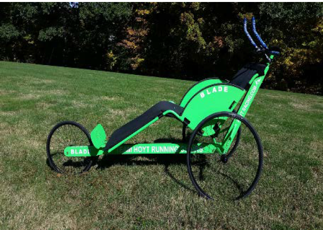
Figure 2.1.5: Hoyt Blade Running Chair.
Figure 2.1.5 shows the high-performance Hoyt Blade running chair. This is the official chair of Team Hoyt, a father/son team where father Dick Hoyt has pushed his son Rick (who has cerebral palsy) in over 1,000 endurance events. This chair is designed for speed and performance. Therefore, large bicycle wheels are used, and the seat is reclined in order to keep the center of gravity low. The chair does collapse, but it does not fold. Instead, pieces of the frame are removable to make it more compact.
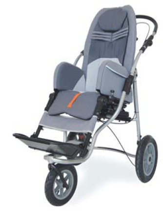
Figure 2.1.7: Tadpole Adaptive wheelchair style jogger.
The jogger shown in Figure 2.1.7 is an example of a wheelchair style jogger. John has told us that Joseph is very comfortable in his wheelchair and that it would be nice if a stroller could put him in a similar position. Due to the short wheelbase and high center of gravity, this would be an unsafe and unstable jogger at high speeds. For these reasons, it would not work for us. However, with this design, it appears that if the wheelbase was extended, the seat could be dropped down; thus, lowering the center of gravity.
DESIGN DEVELOPMENT
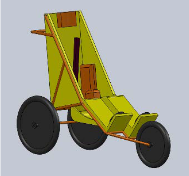
Figure 3.3.1: System Concept 1.
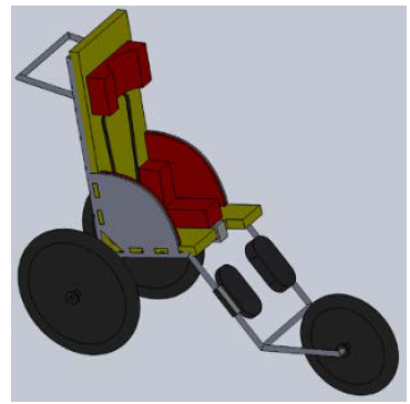
Figure 3.3.2: System Concept 2.
Two full system concepts were chosen based off of the highest scoring subsystem ideas from our Pugh matrices. These two concepts are shown below in Figure 3.3.1 and Figure 3.3.2. The following section will discuss the technical feasibility of our two proposed system concepts. The frame, seat, wheels, harness, foot platform, and brakes will be discussed in detail.
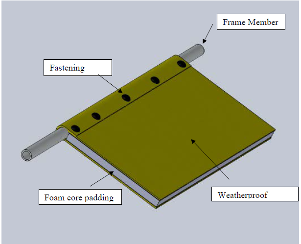
Figure 3.3.2.1: Attaching seat to the frame rails.
Both of our proposed systems use a fabric seat suspended from the frame rails and attached at the lowermost corners to anchors on the frame in order to give it shape. The seat will attach to the frame rails in the manner shown in Figure 3.3.2.1. This method of mounting the seat is used on strollers such as the highly rated BOB stroller. For the seat construction, a layer of foam padding will be sandwiched between two sheets of weatherproof fabric.
FINAL DESIGN
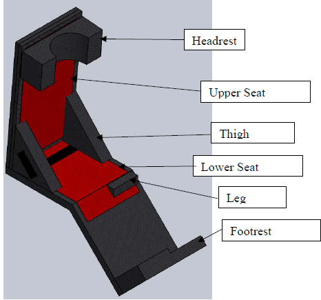
Figure 4.2.1: Final Seat Design.
The seat is divided into individual parts: upper seat cushion, lower seat cushion, headrest, thigh cushion, leg bolster, and footrest cushion as seen in Figure 4.2.1 below. The headrest will help maintain his head from sliding to the side as well as provide comfort. The two thigh cushions will help maintain his position on the seat while giving comfort to his thighs as well as a location to rest his arms. The leg bolster will help adjust his right leg length by displacing about 2 inches.
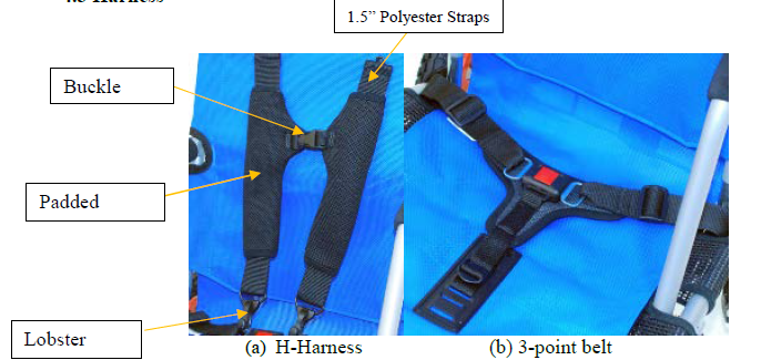
Figure 4.3.1 5-point Harness.
During our design phase, we agreed on going with a 5-point harness that will keep Joseph from leaning or sliding off his jogger. Figures 4.3.1a & 4.3.1b show the H-harness and 3-point belt that will go on Joseph’s jogger. We will purchase the 3-point belt from Convaid, a company that manufactures joggers for children with special needs. Because Convaid manufactures wheelchairs for children, they do not carry complete 5-point harnesses for individuals over 65lbs.
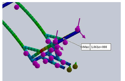
Figure 4.4.1: FEA of the footrest assuming a 100-pound force on the edge. This yielded a safety factor of 5.
The footrest is needed to be able to absorb the large impact forces that Joseph exerts when he pushes against it. Instead of having two separate footrests that adjust to his foot lengths, it will incorporate one long continues plate welded to the frame as shown below. With the piping made from 4130 chromoly steel tubing and assuming that Joseph exerts a 100 pounds onto the footrest, a FEA analysis was done as shown in Figure 4.4.1 which yielded a safety factor of 5, this can be improved by increasing the size tubing from .035 to .065 inch wall thickness.
PRODUCT REALIZATION
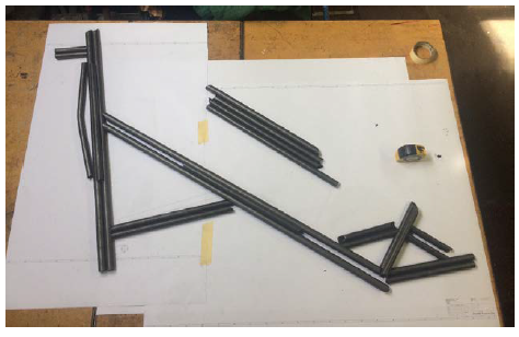
Figure 5.1.1 All the pieces of the frame cut and mitered.
Figure 5.1.1 All the pieces of the frame cut and mitered. The paper underneath is a 1:1 printout that was used to cut the pieces to the correct lengths. Since some pieces appeared similar but were of different wall thicknesses, they were marked with sharpie to ensure we were careful with their placement.
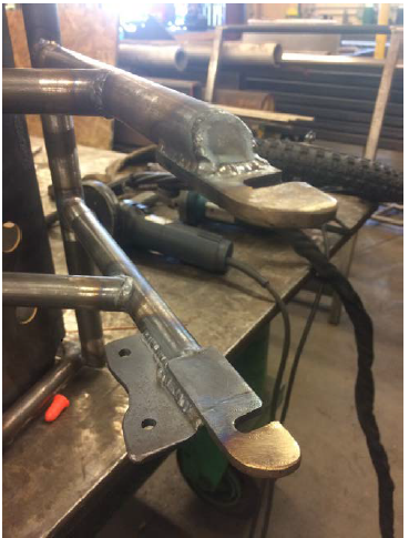
Figure 5.4.2: Finished drop outs welded to the frame.
Figure 5.4.2: Finished drop outs welded to the frame. In order to ensure correct spacing between them when welded, a 100mm spacer was put in-between when they were tacked on. The disc brake mount is shown on the lower fork leg.
DESIGN VERIFICATION
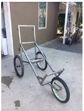
Figure 6.1.1: Initial frame prototype.
To first test our frame dimensions, we created a prototype frame out of square tubing as can be seen in the figure. This frame allowed us to determine that our current jogger model provided was too tight of a fit for Joseph as the frame was too narrow and the Joseph legs extended pass the frame. Additionally, the bar at the back of the frame proved to be uncomfortable even with foam padding and titled the body forward. Using this information, we were able to alter our prototype by increasing the width by 4 inches and length by 3 inches.
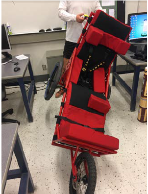
Figure 6.2.2.1: Lean test.
This test was designed to determine the angle at which the jogger would tip if tilted in the horizontal plane. To test this, we tilted the jogger horizontal and measured with a protractor until it tipped. This can be seen in the figure.
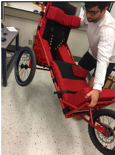
Figure 6.2.5.1: Weight Test.
This test was designed to determine the weight of the completed jogger assembly. Due to our inability to find a scale large enough to measure the jogger, we had Josh Egli pick up the jogger after lifting a series of 45 pound plates for calibration. This can be seen in the Figure 6.2.5.1.
CONCLUSION
This project meant a lot to not only our group, but also to Joseph, his father, and the members of Team Joseph. We are glad to have been able to enhance Joseph’s participation in marathons by providing him with a customized jogger that adapts to his needs. Although we did experience a number of obstacles along the way, the hours put into designing, manufacturing, and testing Joseph’s new jogger have paid off.
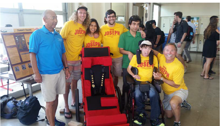
Figure 7.1 Senior Expo (left to right: Michael Lara, Luke Kraemer, Carolina Reyes, Josh Egli, Robert Trujillo, Joseph Cornelius, John Cornelius).
We would like to thank John and Joseph for allowing us to work on this project, our advisor Sarah Harding for guiding us throughout the year and for her endless support, and our sponsor Michael Lara and Team Joseph for their participation and dedication to making Joseph’s Jogger a huge success. As depicted in Figure 7.1, our team not only delivered a successful project to Joseph Cornelius and his father, but we also delivered a part of us that we will never forget. The time we spent with the Cornelius family was unforgettable and this project has been very rewarding!
Source: California Polytechnic State University
Authors: Robert Trujillo | Carolina Reyes | Josh Egli | Luke Kraemer