EXECUTIVE SUMMARY
Lawrence Livermore National Laboratory has invested considerable effort to develop new standard for nuclear grade HEPA filters that can withstand high temperatures along with methods to optimally test not only the experimental filter media, but also new frame seals and media binders. Therefore, LLNL in collaboration with Cal Poly has designed and built a Mini High Temperature Testing Unit (MHTTU) to recreate conditions observed during a fire and to test different materials in an effective, inexpensive, regulated and reliable method.
The existing prototype was unable to achieve the ideal testing conditions of 1000°F air at the low flow rates of 1.25-12 ACFM; therefore, this project looks to optimize previous efforts on building a portable and reliable MHTTU to collect more information and perform different tests in various materials utilized in the construction of ceramic HEPA filters.
Based on previous teams’ inputs, our team performed a heat transfer analysis to determine critical heat loss points and to optimize the design of the MHTTU. After several idea generation sessions, it was decided to modified the geometry of the testing chamber and the insulation of the system. The MHTTU also lacks a robust control system and a user interface; therefore, a more reliable interface and more versatility during the tests were implemented in the system.
With the current design, we were able to improve the maximum temperature of the system to 837°F; however, we were not able to fulfill heat up time of 15 minutes. After carefully recording the temperature of the surrounding material during testing, we believe that the immersion heater is not powerful enough to have an effective heat transfer to air. After testing was completed, it was confirmed that the heater coils cannot reach 1000°F in less than 15 minutes of heat up. Therefore, a more powerful heater is needed to achieve testing parameters.
BACKGROUND
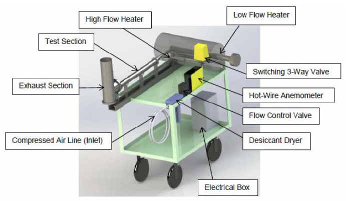
Figure 1. CAD Model of Team Phoenix’s mHTTU.
The original MHTTU, on which Team Daedalus’ project is based, was built in 2014 for LLNL by ME428 group Team Phoenix. The MHTTU can be connected to a canister of compressed air containing whatever contaminants LLNL wants to use to test their filters. The air entering the unit is first heated by a 2 kW Watlow immersion heater, before passing through a 2kW Hot Air Tool. The reason for having two heaters was to help with heating air at low and high flowrates. Team Phoenix found however, that the second inline heater was more detrimental than helpful in achieving the desired temperatures.
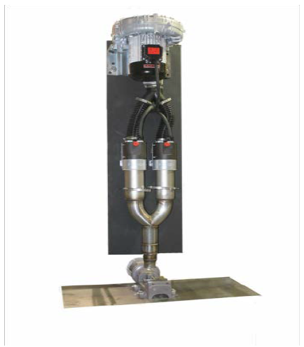
Figure 2. CMI Overhead Thermal Testing Rig.
The CMI OTTR is designed primarily to test joint sealants, but features high temperature air flow as the method of testing [5], meaning it is reasonable to compare to the design specifications from LLNL. Unfortunately, the high temperature aspect of the OTTR is the only verifiable similarity to this project’s goal. The OTTR can reach temperatures of up to 1100 °F, but CMI provides no information regarding the range of the air flowrates it is capable of.
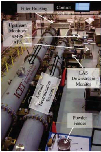
Figure 3. ICET Generic Test Stand.
The ICET was designed at Mississippi State to perform lifecycle testing of HEPA filters, including nuclear grade filters like the ones that LLNL will be testing with the MHTTU. Unlike the MHTTU however, the ICET is built to test flowrates between 500 and 4000CFM, far exceeding even the maximum desired flowrate desired by Team Daedalus. The ICET is also built to be a low temperature testing apparatus, with air temperatures ranging between 60 and 140 °F, which also does not match the specifications for the MHTTU.
DESIGN DEVELOPMENT
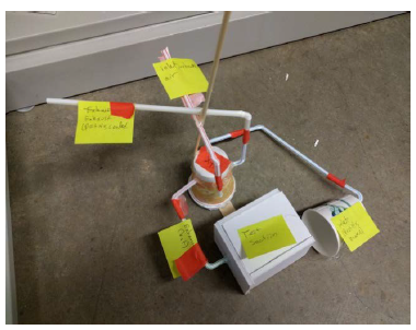
Figure 8. Heat exchanger prototype.
An option that was investigated for viability, effectiveness and cost was implementing a heat exchanger to divert the waste heat coming out of the exhaust to preheat the low temperature air entering the heater. Preheating the air entering the heater would decrease the heater power demand and increase the overall efficiency of the system. Although it is acknowledged that perfect exchange of heat is impossible, a heat exchanger may prove to improve efficiency when paired with a proper system. The model of the heat exchanger is depicted in Figure 8.
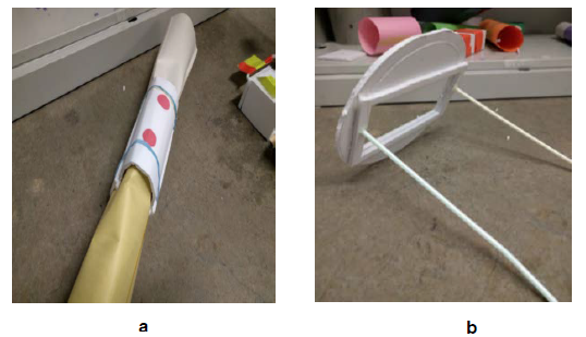
Figure 12. Prototype of a) cylindrical testing chamber with its respective b) detachable sample fixture.
A total change to the chamber geometry would also necessitate repeating any thermal analysis done by Team Phoenix and Team MicroFire to determine the air flow and heat transfer characteristics of new geometries. FEA and CFD models, along with conventional analytical examination, will provide objective evidence for the ultimate decision regarding the chamber geometry. A prototype of the cylindrical testing chamber with its respective detachable sample fixture can be found in Figure 12.

Figure 13. Flow diagram of upgrades to implement in MHTTU.
An Arduino micro-controller was selected for this application because it is capable of being inexpensively expanded to include extra features such as wireless communication, touchscreen/controller integration and graphics output. It is also capable of Microsoft Excel integration with the proper program. Having this flexibility would have aided in getting the control system to a level that satisfies our specifications. Also, it was recognized that a well-documented control system is desired for this application.
DESCRIPTION OF FINAL DESIGN
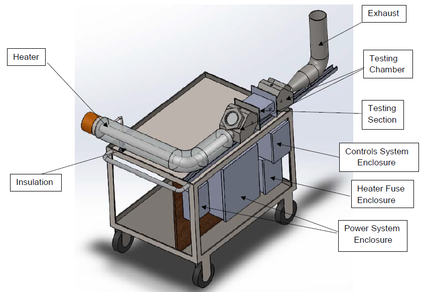
Figure 14. CAD model of current MHTTU.
After investigating possible modifications to the existing MHTTU and discussing them with our sponsor, it was concluded that the best path forward was to work toward the mitigation of heat loss from the testing chamber. To minimize heat losses, new methods of insulation on the cold side of the MHTTU were investigated, along with modifying the inside surface of the testing chamber to decrease the ability of the stainless steel to absorb heat meant for the test section. Additionally, geometric modifications were investigated, including removing as much mass as possible from the test chamber and test section, to decrease the ability of the assembly to absorb heat from the process air, and dissipate it to the ambient air.
PRODUCT REALIZATION
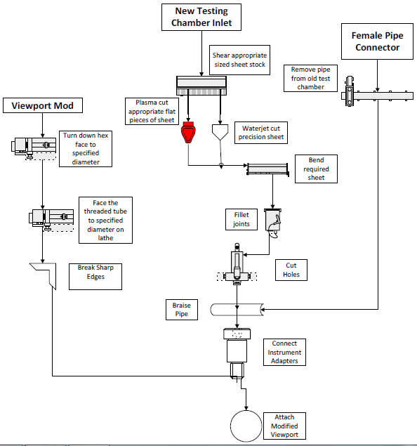
Figure 21. Manufacturing Flow Chart for Viewport and Inlet Test Chamber.
Because the main focus of team Daedalus was to renovate and improve previous attempts to build the MHTTU, the manufacturing of the system was tailored to new test chamber, new chamber inlet and outlet, and modification of the viewport glass. The manufacturing plan for the MHTTU can be seen in figure 21.
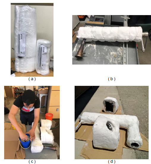
Figure 26. Application process of (a) ceramic wool insulation, (b) insulation tied up with tie wire, (c) insulation covered with adhesive mesh drywall joint tape, and (d) insulation covered in plaster.
gauge. Finally, the insulation was covered with a layer of adhesive mesh drywall joint tape and cover by three layers of plaster. This method was used to accomplish a finish that would allow future modification, but at the same time provided consistency, support, and coverage for the insulation. The application process for the ceramic insulation can be seen below in figure 26.
DESIGN VERIFICATION
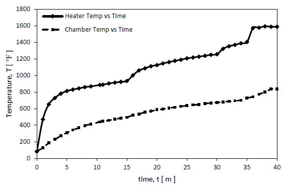
Figure 29. Graph of Temperature vs Time of Test One (Embedded Data).
Lastly, the air pressure was dropped to its minimum pressure allowed by the equipment of approximately 2.5 psi. With this air pressure, the maximum temperature measured at the heater coils was 1540 °F, and the maximum recorded temperature in the inlet test chamber was 835°F. these temperatures were recorded after 45 minutes of testing, and the data collected can be observed bellow in figure 29.
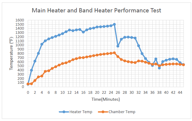
Figure 30. Graph of Temperature vs Time of Test Two (Embedded Data).
Figure 30. Graph of Temperature vs Time of Test Two (Embedded Data) Unfortunately, we cannot determine how much of this improvement came from the introduction of the band heater and how much from the low flow rate. We hypothesize that it is a combination of both and that low or no flow conditions with the band heater should be the next set of tests to be done.
CONCLUSIONS AND RECOMMENDATIONS
Unfortunately, Team Daedalus was not successful in accomplishing a system that meets the specifications of Lawrence Livermore. The primary catalyst for the failure was the 2 quarter long delay in getting a working power system that was safety approved for on campus power-up. The control system remains incomplete as of the end of senior project, so our primary suggestion is to complete the debugging of the code. We suggest future teams start with figuring out how to get the Arduino to return a value to Instrumentino though serial. Then we suggest modifying the PID library to accept an integer rather than poll a voltage.
From the testing that was done, we hypothesize that our modifications, while they did improve the thermal capabilities of the system, did not address every heat leak in the system. Little heat was felt leaving though the insulated parts, though there were a few areas that did feel hotter than others. These places could do with more insulation to prevent heat losses, but the effect would probably be minimal. We would suggest for future teams to perform FLIR or other thermal camera testing to see where heat leaks are.
In our testing though, major amounts of heat were found to be leaving the system though the brackets that join each section together, so one recommendation we make to future teams is to explore the possibility of either welding the inlet test section to the heater section to remove the need for the brace, or simply insulating the brace.
Team Daedalus also was investigating alternative heaters that were more specialized at heating air. The idea behind that was since the immersion heater is designed for stagnant liquids, that flowing air would not be able to fully utilize the heaters energy due to a small surface area. Should further insulate improvements still not produce the desired results, we strongly recommend that future teams look into alternative heaters. This was hypothesized by team Daedalus, but due to lack of evidence and a high cost we were not able to get sponsor approval to buy a new heater.
Source: California Polytechnic State University
Authors: Kevin Liu | Pablo Castillo